Verifying Use Cases, Data Flow Diagrams, Entity Relationship Diagrams, and State Diagrams via State Linkages.
Verifying Use Cases, Data Flow Diagrams, Entity Relationship Diagrams, and State Diagrams via State Linkages
The purpose of this brief article is to provide a simple example on how to link and verify four models: use case, data flow diagrams, entity relationship diagrams, and state diagrams. Note the word verify, not validate. Verify in this context means that the technique is consistent and complete, not that it reflects correct requirements.
In writing this article, the author assumes the reader understands the four models mentioned above. With this understanding, the article focuses on the relationship between the models via states.
Use case is an alternative technique for documenting functional requirements for interactive operational systems. It models a dialogue (a process) between a user (actor) and a user goal (use case). The technique consists of a diagram and a description. The description of a use case includes pre and post conditions.
- The precondition is the state of the application that is guaranteed to exist in order for the use case to start (no precondition checking within the use case)
- The post-condition is the state of the application that is the result of the success or failure of the use case (state change must be a step within the use case)
Hotel Application Example
Let’s say a hotel desk clerk has five goals: create reservation, confirm a reservation with a credit card, fulfill a reservation, cancel a reservation, and close a reservation. In this case, the hotel application tracks reservations via a “state”attribute for a reservation. Each time the hotel desk clerk executes a use case, the hotel system either changes a reservation’s state to an appropriate value or leaves it unchanged. Figure 1 depicts the Hotel Application.
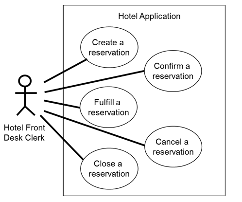
Figure 1. Use Case Diagram for Hotel Application
Use Case Pre and Post-conditions for Hotel Application
Below are the pre- and post-conditions for the five use cases needed by the hotel front desk clerk. These conditions are contained in each respective use case description (for brevity not shown).
►Create a reservation
- Precondition –there is no customer reservation (i.e., no precondition)
- Post-condition for success – the customer reservation is created with a state attribute having the value of “opened”
- Post-condition of failure – the customer reservation is not created
►Confirm a reservation
- Precondition – the customer reservation exists with its state attribute having the value of “opened”
- Post-condition for success – the customer reservation exists with its state attribute changed to the value “confirmed”
- Post-condition for failure – the customer reservation continues to exist with no value change to its state attribute
►Cancel a reservation
- Precondition – the customer reservation exists with a state attribute having the value of “opened” or “confirmed”
- Post-condition for success – the customer reservation with its state attribute changed to the value of “cancelled”
- Post-condition for failure – the customer reservation continues to exist with no value change to its state attribute
►Fulfill a reservation
- Precondition – the customer reservation exists with its state attribute having the value of “open” or “confirmed”
- Post-condition for success – the customer reservation exists with its state attribute changed to the value of “fulfilled”
- Post-condition for failure – the customer reservation continues to exist with no value change to its state attribute
►Close a reservation
- Precondition – the customer reservation exists with its state attribute having the value of “fulfilled”
- Post-condition of success – the customer reservation exists with its state attribute changed to the value of “closed”
- Post-condition of failure – the customer reservation continues to exist with no value change to its state attribute
Note that in each use case description there needs to be a scenario step that sets the value of the reservation state attribute depending on the success or failure of the use case.For example, at step 10 of the “Confirm a reservation”scenario:
...
10. The hotel application changes the reservation state to “confirmed”
...
This value of the state attribute is then the precondition guarantee for any future use case execution.
Linkage to Other Models
Use case is a process model. However, our hotel application also uses data attributes, in particular “reservation state” to track its status.For consistency and completeness, the attribute “reservation state”needs to exist in a
►Data flow model – Data Flow Diagram
- A Data Flow Diagram (DFD) models data as it flows through the business processes and into various data stores (Figure 2).

Figure 2. Data Flow Diagram for Hotel Application
- For the hotel application, the DFD needs to show the reservation state changes after it passes through a hotel process. This is the same reservation state shown in the use case pre- and post-conditions.
►Data model – Entity Relationship Diagram
- An Entity Relationship Diagram (ERD) models entities, their attributes, and their relationships (Figure 3).

Figure 3. Entity Relationship Diagram for Hotel Application
- For the hotel application, the ERD needs to show the reservation state attribute residing in the Reservation entity. This is the same reservation state shown in the use case pre- and post-conditions and the data flow diagram.
►State model – State Machine Model
- A State Machine Model models the value sequence of various state data items in an application (Figure 4).

Figure 4. State Diagram for Reservation
- For the hotel application, the State Machine Model needs to show the sequence of the valid values for the reservation state (open, confirmed, fulfilled, cancelled, and closed). This is the same reservation state shown in the use case pre- and post-conditions, the data flow diagram and the entity relationship diagram.
Summary
The state attribute is the logic glue that holds these models together. The analyst needs to verify the models for consistency and completeness (Figure 5).

Figure 5. Reservation States between Models
Questions for Checking Consistency and Completeness of Models
- Are Use Cases, DFDs, ERDs, and State Machines models consistent and complete with each other?
○ Are state changes shown as use case pre- and post-conditions?Use cases model the functions that set states.
○ Are state changes shown in information flows?Data flow diagrams model the processes that transform states.
○ Are state attributes shown for entities? Entity relationship diagrams model entities and their states.
○ Are valid state values shown in sequence?State machine diagrams model the sequence of state values.
Comments
Post a Comment